What appears on the drawings
Plans identify device locations and identifiers; risers show interconnections; schedules tie each endpoint to cable, pathway, power and head-end equipment.

Document the design so field teams, facilities staff and reviewers can work from the same plan.
Greater Denver and the Front Range
Products, interfaces and exact scope are confirmed after reviewing the facility.
Drawing requirements vary by project and jurisdiction. We coordinate the applicable review and approval path during scope development.
A useful drawing set connects device symbols to actual locations, pathways, power sources, network drops and equipment schedules. During the project, changes need to be marked so the final record reflects the field condition.
Marked-up changes and final as-builts help service teams understand what was actually installed.
We confirm existing conditions and customer responsibilities before finalizing products, interfaces, tests and the documentation needed to support the installed system.
A useful design connects components, people, failure conditions and a testable handoff.
Plans identify device locations and identifiers; risers show interconnections; schedules tie each endpoint to cable, pathway, power and head-end equipment.
Resolve door hardware, ceiling conditions, rack elevations, conduit ownership and fire or life-safety interfaces against architectural and electrical documents.
Track field changes and reviewer comments by revision so installers and other trades work to the same approved set.
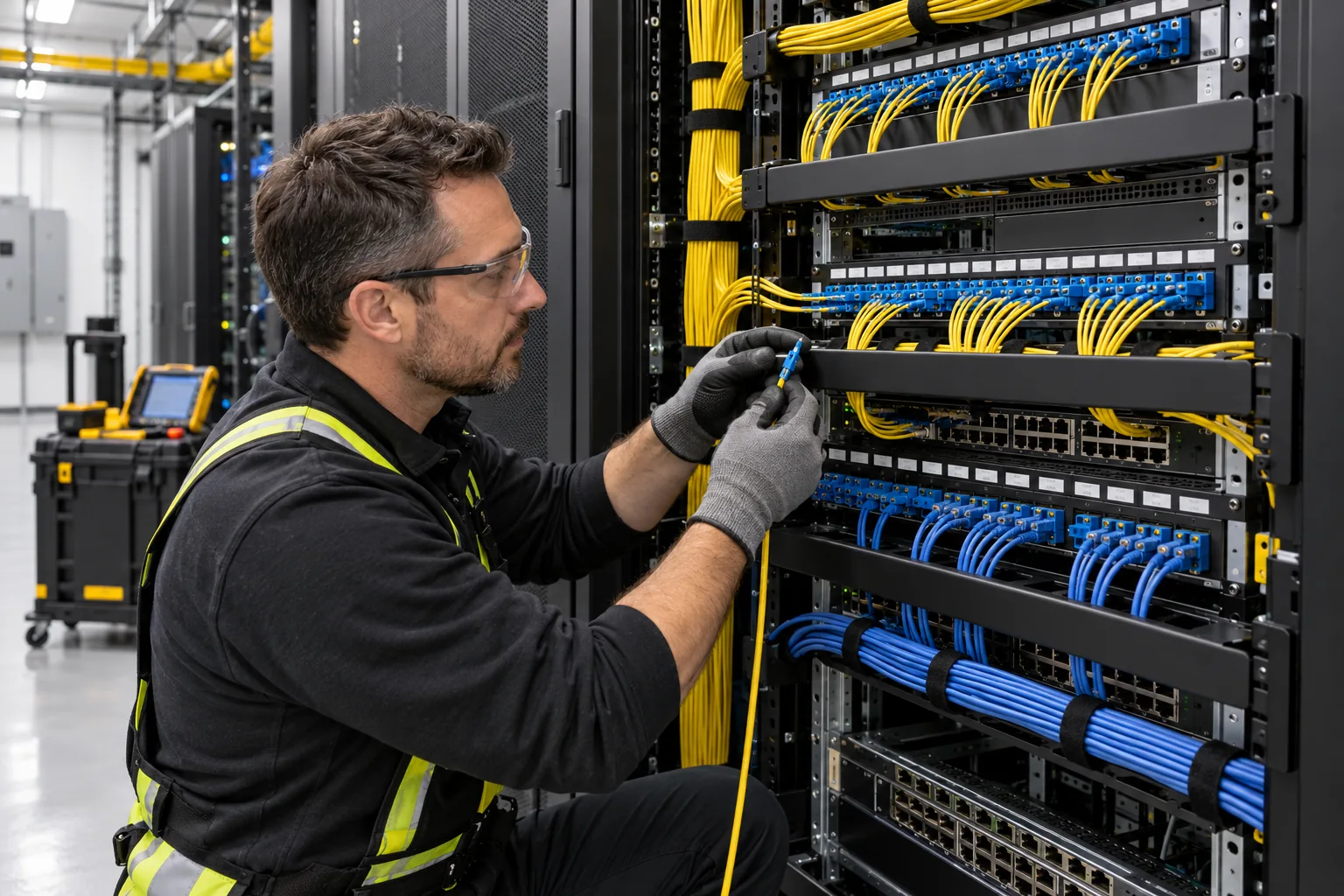
Record as-built locations, panel identifiers, termination references and accepted deviations so future troubleshooting starts with the actual installation.
Five possible applications to explore during discovery. These describe capabilities and design scenarios, not completed customer projects.
Draw reader, lock, request-to-exit and door-contact locations for each controlled opening.
Create camera schedules with mounting heights, intended views, network drops and power.
Prepare riser diagrams that trace field devices to panels, switches and backup power.
Coordinate conduit, cable routes and equipment-room elevations with other trades.
Record field changes on as-built drawings so the service team can find the installed equipment.
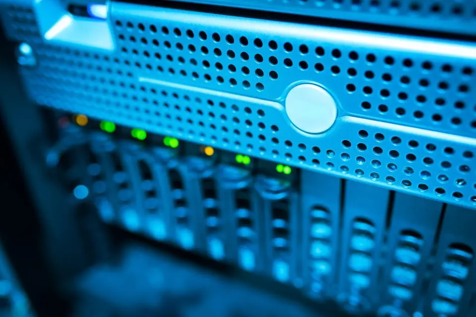
Representative equipment and working environments relevant to the scope.
Our pre-site safety review, field documentation and customer acceptance process help keep the installed condition visible to the people who will operate and maintain it. For engineered drawings, the closeout conversation should include: Record as-built locations, panel identifiers, termination references and accepted deviations so future troubleshooting starts with the actual installation.
We ask for the existing drawings, device inventory, network and power ownership, known deficiencies and the people who will use the system. The final scope and acceptance criteria follow those answers.
| Decision | What to confirm |
|---|---|
| Scope | Confirm the devices, areas and operating modes included in the work; record exclusions. |
| Dependencies | A useful drawing set connects device symbols to actual locations, pathways, power sources, network drops and equipment schedules. During the project, changes need to be marked so the final record reflects the field condition. |
| Handoff evidence | Record as-built locations, panel identifiers, termination references and accepted deviations so future troubleshooting starts with the actual installation. |
Have a building in Colorado? 1st Key stands ready and able to help. Tell us the location and what needs attention; we will confirm service availability and scope.
Describe the facility, the existing equipment and the outcome you need. We can discuss design, deployment or service.